In this article I will explore with a question of interpretation of the interference fringes, by means of the interferometer Newton, during the analysis of the optical surfaces.
As already described in this article, the evaluation of the profile of the convex surface is performed picking her compare with a reference surface (concave) that can be spherical, parabolic or same conical constant of the surface to be analysed depending on the degree of deformation of the optic.
Once ending the polishing of the concave caliber and obtained the desired shape, with an accuracy of at least lambda / 10, You can analyze the mirror surface using the interference fringes that return some sort of level lines corresponding to the distance between the two surfaces under analysis.
This type of test is also often used to test the flatness of an optical surface. In this case, however,, it will be necessary to have a gauge with a flat reference surface (with an accuracy of at least lambda / 10) on which adagerà the surface to be analyzed to obtain the interference pattern, and then the information to determine the shape of the optical under analysis.
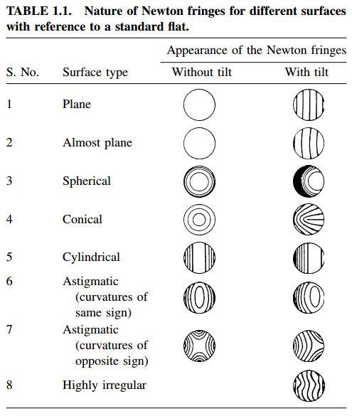
The classic forms that the fringes can assume in this case are shown in the table below, grouped into two columns: without the presence of a tilt (No inclination) between the two surfaces and the other with the presence of tilt (inclination between the two surfaces).

In the figure below instead, we can see an example of interference fringes between two surfaces, one optically flat and the one under examination.

As you can see the lines are not perfectly straight and this indicates the non-perfect flatness of the surface in examination, which in this case it turns out to have a maximum deviation with respect to the flat surface by an amount approximately equal to lambda / 4 (this is because the maximum distortion of the central line is equal to approximately half the distance between a fringe and the other, and between a fringe and the other there is always a difference of 1/2 lambda).
That is, the surface under examination is non-planar, but it is to be considered as a spherical surface with a great radius of curvature, so as to be almost flat.
The radius of curvature of this surface, however, It could be either a concave surface and a convex (in relation to the flat) and it would present the same shape of the interference fringes in both cases.
Is’ therefore necessary to have a method that allows to discriminate between the two possibilitiess.
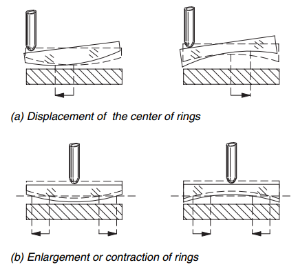
The method consists in exerting a slight pressure above the surfaces through fine test, and observe the direction in which the fringes move.
This method it can perform both exerting the pressure in the vicinity of the edge and exerting the pressure at the center of the glass with the following results.

As you can see from the above table if you press near the edge and the fringes move in the opposite direction to the point of application of pressure it means that the surface under analysis is concave, while if they move toward the point of application of the surface pressure is convex.
If the pressure is exerted in the middle, you will see the circular fringes move to the center if the surface is concave and outward if the surface is convex.
P.S: pay close attention to the meaning of concave and convex in this particular analysis method, as it can lead to gross misinterpretations, especially when under analysis there aren't two flat surfaces but two spherical surfaces (parabolic, Hyperbolic etc ...)
To remove all doubt from misinterpretations always remember that:
- Surface under convex analysis = the two mirrors are touching in the Center and there is gap at the edges.
- Concave surface under analysis = the two mirrors are touching the edges and there is gap at the center.
Through these considerations it is possible to understand if the surface under analysis have greater or less than the radius of curvature of the caliber and vice versa.
There are other simple tests that allow to discern a convex or concave lens that you can find a description of the pages from 6 e 10 the following book: "Optical shop testing" in Daniel Malacara, from which all images were drawn in the article.