Forum Replies Created
-
AuthorPosts
-
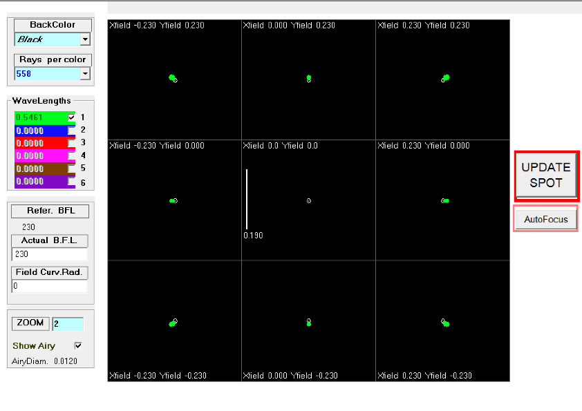
As you can see, un 200F9 (parabolic) gives a correct range of 15 mm focal plane, where the spot size is smaller than the Airy disk ( white circle ).

Interesting discussion…
I think that the cpl should be designed also taking into account the resulting correct field which, for a newton f9 is definitely higher than i 6 mm.
Atmos provides some great simulation tools for light spots, which allow to evaluate the extension of the corrected field on the focal plane.
An optical project always has to deal with a series of compromises, in this case, an extended focal plane is dispensed with in favor of less obstruction.
Whether it is the right thing to do can only be determined by the user of the tool… I personally would have chosen a greater obstruction to fully exploit the wide corrected and flat field of an f9 dish.I agree with Giulio, in this case I don't think the difference between the two obstructions is perceptible.
Ciao Andrea e benvenuto !

Other materials including silicon carbide ( which it seems to be better than the glass also ) They are used to produce optical , Zygo has even list them:
https://www.zygo.com/?/opt/components/mirrors/siliconcarbidemirrors.htm
the James Webb Space Telescope mirrors are beryllium, which in any case it is a metal…
from wikipedia:
The primary mirror is constituted by 18 hexagonal elements beryllium flanked honeycomb. Each individual mirror, the size of 1,4 meters, It is covered with a thick gold foil 1000 Angstrom (100 nanometers high.), which better reflects the infrared light.[21] The gold foil is in turn covered by a thin layer of amorphous SiO2 (glass) to protect it from scratches when handling or small particles. In the launch phase the primary mirror is compacted in 3 sections and stowed in the rocket; subsequently it deployed with micromotors. The optical technology of JWST consists of three mirrors anastigmat. In this configuration, the primary mirror is concave, the secondary is convex and it works slightly off axis; the tertiary mirror removes the resulting astigmatism and also flattens the focal plane.[21] This also allows a wide field of view to produce images without optical aberrations. It is also used a fast power steering system to enable image stabilization. The optical unit is provided by Ball Aerospace & Technologies Corp. sub contractor Northrop Grumman Aerospace Systems.L’ossido di alluminio ha un buon potere lucidante, tuttavia è difficile trovarlo a granulometria controllata, ( e quando lo si trova il prezzo aumenta ) il che significa che tra i normali granuli di dimensioni medie di due micron adatti a lucidare il vetro, c’è una percentuale significativa di granuli di dimensioni maggiori che generano righe e solchi sulla superficie impossibili poi da togliere se non tornando indietro con la smerigliatura e carborundum.
Inoltre l’ossido di alluminio è un materiale poco tenace, se si osservano i granuli al microscopio si può vedere che essi sono costituiti da bordi taglienti ed affilati ma che solo dopo poche passate si arrotondano e perdono la capacità abrasiva e lucidante. Quindi si è costretti ad un ricambio ed utilizzo maggiore rispetto all’ossido di cerio.D’accordissimo con Giulio, oltretutto i due vetri offrono più controllo sulla regolarità della superficie che si sta lavorando fin dalle prime fasi, si arriva alla lucidatura con una buona percezione della qualità della sfera semplicemente osservando l’uniformità della distribuzione delle bollicine d’aria nella miscela abrasiva tra i vetri.
hello Fabrizio, welcome !

Stefano, Ronchi respect to the procedure and the meaning of the parameters is what you described.
The offset value allows you to display one or more bands depending on the needs of the moment, then the value is always a choice of who performs the test.
Another parameter that can be used, during parabolizzazione, is the value of the conical constant ( K = 0 sfera , K = -1 parabola ) in intermediate values, during the intermediate stages, to get an idea of the point reached with the processing.
The only thing that I would recommend, when comparing simulations of the software with the test images, is that the value of the lines / mm ( ad is.: 4 lines / mm in the software indicates 4 dark lines + 4 transparent lines for a single width line 0,125 mm ) It has occurred and exactly the same as that set on the software, otherwise the images are not comparable.
Hi Stefano, welcome back !

and Luke, the degree of sanding generated by grit 800 unfortunately it is not sufficient for a correct reflection. If you look at your microscope with the surface, however, you will see the tiny craters which have still larger than the wavelength of light, this means that the light incident on the glass wave is reflected in several directions. For this reason you can not do the Ronchi test, since the reflected light is diffused light, while we need that the reflection occurs in the focal plane for examining the characteristics.
When the glass is polished to the point that we can see his own reflection, then you can execute the Ronchi test, but this may not occur before the passage of cerium oxide with pitch tool.hi Luca, I did not understand what you mean by “The mirror surface was polished with 800 grit″…
I mean if:
1- the surface is still in the process of grinding with the grain 800 and the tool “rigid”
2- the surface is in the process of polishing with cerium oxide and tool pitch.-in the first case, the Ronchi test can not be performed because the surface is not reflective.
-in the second case the problem is in the correct realization of the tester.he ( and only if ) the surface is glossy and reflective, then you need to optimize the tester, first of all finding the exact size of the slot in front of the light source, without which the test can not produce legible results.
A rule of thumb says that the slit size should not exceed the distance between two grid lines, namely for a lattice from 4 linee/mm, DIM. maximum of the slot is of 0.125 mmhello Antonino, It is difficult to answer without knowing the telescope in question, I think it has been designed and built with the hood dimensioned that way have had their own reasons. Besides, I am not an expert and photographic techniques I could not guess what would be the influence of changes to the hood.
What is certain that the hood acts mainly on two aspects:
– protection from external sources / reflections to the optical cone
– the size of the field of full light, beyond which begins the vignetting and the consequent decrease in brightness on the focal plane. By removing the lens hood the CPL would be limited by the size of the secondary ( usually it made larger than necessary to avoid having to use the critical zone of the edge, hidden just by the hood ) and the central hole on the primary, consequently would increase the full-brightness area on the focal plane and at this point come into play the size of the sensor used for the acquisitions, which might be such as to be affected by the change of setup.therefore, if you've already ruled out other possible causes, an attempt to capture without a hood I would, if only to see if and how to evolve the malfunction you're experiencing.
You can groped a simulation to reconstruct the original scheme which, however, will not provide any guarantee to match the telescope in question, for two main reasons:
1- at least one of the two optics should be constant and known for focal conic.
2- the distance between the mirrors is of course that measured, but it is said that it is the project that is the correct and necessary. The telescope will definitely have a longitudinal adjustment system to vary the position of the secondary along that axis. If the current of the secondary position was different ( Also very little ) from design, then also this parameter would be unknown and there are infinite configurations that can verify the schema.
An important indication of the real goodness and optimization of the whole system could come from a star-test.
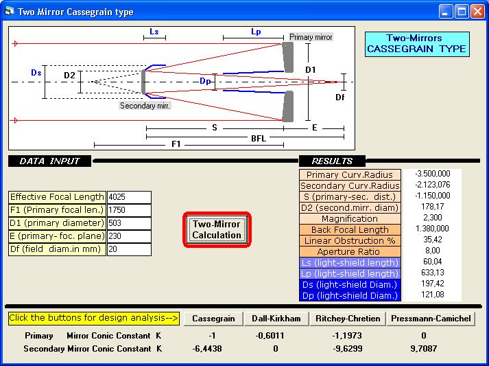
Having said that we try equally to hypothesize a possible RC scheme with the data available to have an estimate of the size deil hood.
in this simulation, the primary diameter has been reduced to 503 mm whereas there will surely be a chamfer at the edge of the non-reflecting mirror.
Let us then an RC schema that returns the values known to us :
To say that this is the original design would be like betting lottery, however, the system should not differ much from this hypothesis, we will definitely optimize everything with these data, but we can make an assessment on the primary lens hood, the object of our investigation, which should be longer ( and consequently wider ) to ensure that the cone of light seen from the back focus is fully protected from external reflections.
Obviously this applies whether we are talking of a telescope “open” with a lattice intubation, It would be different for a closed tube in which the lens hood of the primary may not be necessary and in any case not in these dimensions.
It is interesting to see that, to obtain this distance between the mirrors, with this back-focus, the primary should be a F3.5
hello Antonino, I confirm the Back-focus 150 mm? this measure should be understood from the center of the mirror ( from the reflective ) to the focal plane.
-
AuthorPosts