Forum Replies Created
-
AuthorPosts
-
The excavation continues with a patina of pitch and cerium oxide, the races a “W” generate a good parabolic shape, but they are not very suitable for reaching depth “quickly” while tangential runs along a circumference dig quickly, but maintaining the shape is difficult and must be interspersed with strokes a “W” to connect the zones.
So, I thought and found an alternative that is able to generate depth quickly and at the same time generate a parabolic shape.
I called them “run to Y”
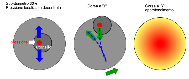
The following diagram shows the setup and execution of the technique for a sub-diameter al 33% ( what I am using )
All you have to do is imagine you are performing straight runs center to center while the mirror moves on a rotating plane.
If you don't have a rotating table available, straight runs are performed ( not with respect to the mirror but with respect to oneself ) while moving fairly quickly around the table.
With one important difference: the pressure should not be applied to the center of the tool but should be decentralized by at least 1/3 the diameter.This aspect is important, why the COC runs with sub-diameter, generate a spherical shape in the mirror area that has the same extension as the tool, and even if they dig more in the center of the mirror, the resulting shape will be quite far from the parabola.
the off-center strokes instead allow to create a machining asymmetry in which the center , at every run, it is always affected by excavation while the remaining areas undergo a minor excavation action depending on the distance from the center.
– the offset must be small but not zero or, even worse, “negative” ( otherwise they create “steps” in the middle area.
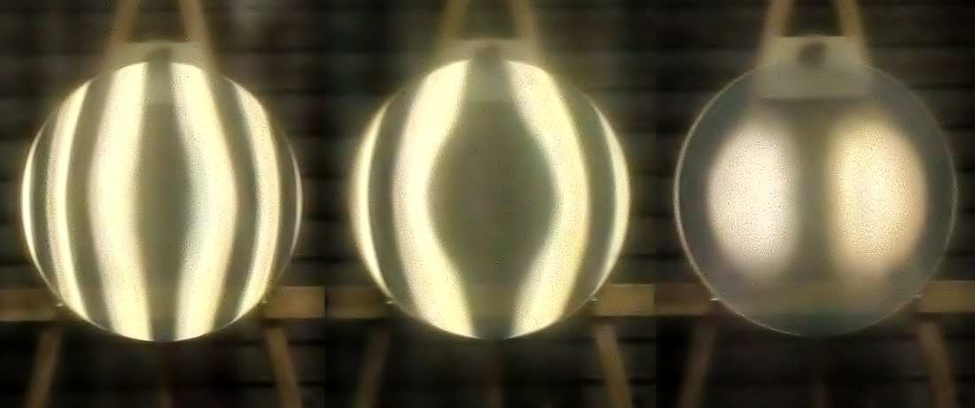
– movement around the table must be fast enough ( but not too much ), the “Y,” that is, it doesn't have to be too much “hold” nor too much “long”.Below, the images after a few sessions with this technique without performing other connecting runs.
With a few sessions ( morning + part of the afternoon ) the center was excavated 10% the required depth. In fact now the conic has reached a constant of K =-0.2, while before this process it had arrived ( with difficulty and difficulty in maintaining shape ) a K=-0.1

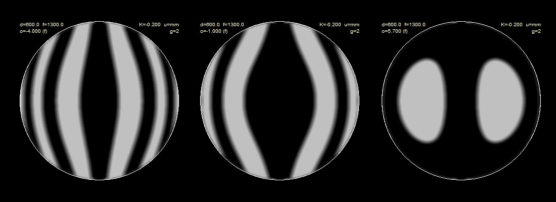
– the “step” seen in the middle area is now almost absorbed, but in the beginning it was generated precisely because I had performed the Y runs without touching the mirror edge and therefore the median area remained a little’ higher than it should, as can be seen by comparing the images with the simulation of Ronchi for K =-0.2.
I understand the difficulty.
I don't know if you already know what follows, in case parabolization could help you ... since you have always "the best you touch", always managing to turn the result in your favor
 .
.Giulio, I thank you for your trust, but I don't think so ( maybe!
 )…
)… And, we talked about it some time ago with you and Mirco, both of Mel's work and of the different methods of using the Ronchi with supporting images… I remember that Mirco had also proposed a print of the Ronchigram to be applied on the mirror during testing.
Anyhow, with all respect and admiration for Bartel, I always stay a while’ perplexed when it is proposed to finalize an optic with the Ronchi.
for charity, the Ronchi is a formidable and very helpful tool, but I think it should be used for what it is in its nature and that is, provide an overview of the optics, to highlight zonal irregularities, folded edges, astigmatism and roughness, but I don't think we can expect to measure something with an instrument which by definition does not give measurements or numbers as a result.
Moreover, if for mirrors around F6 the detection of the minimum error is visually quite good ( around lambda / 10 ) as the focal ratio decreases, the size and distance of the reticle lines increase, therefore consequently the minimum detectable error increases.
In a reticle F3 2 linee/mm ( admitted having a view from “falco” ) is around lambda / 2, in an F2 it is higher than the lambda.Personally, I use the Ronchi only in the construction of the sphere and in the phases of approach to the parable, ( as well as for the aspects mentioned above ), but I would never dream of making a parable with Ronchi alone, I would not be able and I do not understand how it is possible to evaluate a correction expressed in wave fractions with a grating that provides an approximation greater than the required tolerance , with the addition of the “subjectivity” of the operator who measures nothing but visually evaluates a deformation, even with all the help of overlapping masks or images,
The usefulness of the Ronchi lies in the simplicity and speed of the test, in practice it is immediate and provides an excellent overall evaluation and is fine until the time when the measures are not necessary.
I will try to reach the parable for this F2.2 in progress with Foucault , starting to use it as soon as I reach a conic constant ( estimated with the Ronchi, even crudely ) of at least K =-0,7 .
Subsequently, in the vicinity of K = -1 ( with all the limitations of Foucault for fast mirrors ), I will use the long and laborious but very precise caustic test to arrive at the final hyperbola, which differs little from the paraboloid ( K=-1.12 )
The study continues in small steps…

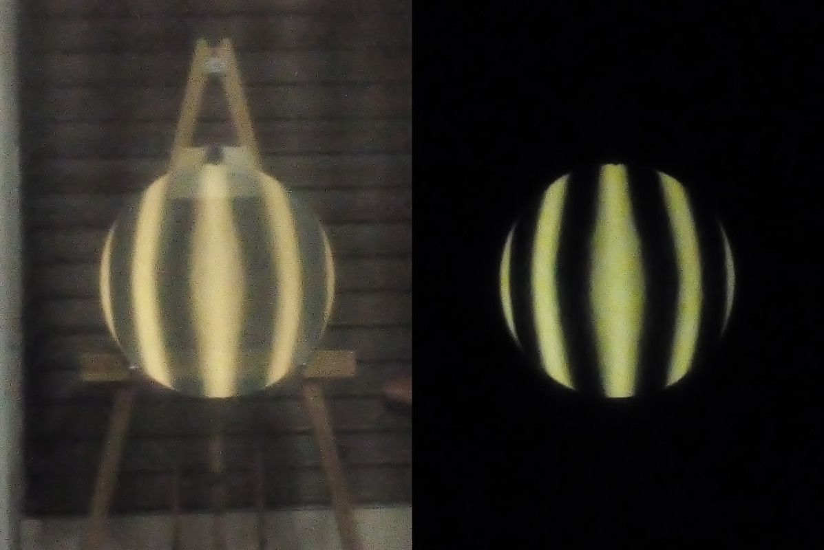
In the image on the left, I forgot to turn off the light before taking the picture. On the right instead, I remembered it


For further information I am using only tangential rides along the circumferences of the central areas, interspersed with a few laps of W races ( even these power plants without ever reaching the edge completely ) to make the worked areas uniform.
It Giulio, in practice it is, it becomes difficult if not impossible to make local or zonal assessments, the problem is in the 7 hundredths of mm of difference in the radii of curvature between center and edge, in a surface at f2.2… For nanometer sensitive tests like Ronchi and Focault they are really too many to handle.
This is a simulation of the mirror in question with a 4L / mm grating, so enough already “long”, which in theory could also read lambda / 4 ( the wider the lines of the lattice, the greater the extent of the minimum detectable defect ) .
To improve the reading of the lines it would be necessary to further widen the lines of the reticle and reach up to a single line per millimeter, but in doing so the sensitivity of the test to error would be higher than the lambda.
In the image, the test done with a 4-2-1 linee/mm

Thanks Giulio
 even if you scared me
  you missed an extra zero ! fortunately the nanometers to be removed are “solo” 70.000
However, a few hundred nanometers ( perhaps 1000 ) I have certainly dug them and you are starting to see some timid signs of deepening, therefore there will remain yes and no others 69.000
  , nanometer more, nanometer less…
the beautiful ( so to speak ) is that the Romchi test can be used for a little longer, only in these early stages still close to the sphere. The focal ratio is so high that as soon as the conic constant begins to assume values lower than -0.3 ( or so ) the test itself will become almost unreadable.
Thanks Mirco

A little less than 7 cents mm ! This is what it will take to dig to parabolize the mirror

Anyone who has already scratched a parable knows very well that this “small” value represents hours and hours of work with pitch , cerium oxide and elbow grease !

I have already started the study, I will not follow the classic and very used processing at 70% ( deepening of the center and of the edge, leaving the area al 70% the diameter ), although this will involve more excavation ( in a smaller area though ).
Digging the edge frankly worries me, with these radii of curvature so pushed I saw that to find a nice riveted edge, ( then difficult and challenging to correct in a F2.2) even a single session in which the longitudinal overflow of the tool during the strokes is greater than the transverse one may suffice.
The excavation will be done all in the center, the edge will be treated as little as necessary.
I have not yet taken pictures of the small deformation achieved so far, therefore I publish the immediately preceding ones, when the sphere was now corrected by any astigmatism even if it still needed a better connection between the worked areas, as can be seen from the bands of the Ronchi slightly “rough” and not really straight. It must also be said that the smartphone is generally not the best for taking photographs of this kind, they succeed best with a very simple webcam which, however optically “low” and economical, it allows a better management of exposure and contrast with dedicated controls, much better than the automatisms of a mobile phone. See you soon with the first images of the mirror on the way to the parable.
 5 November 2020 at 0:42 in reply to: POLISH AN ULTRA FAST MIRROR WITH NON-NEWTONIAN LIQUID TOOL INSTEAD OF PITCH? #12037
Very interesting Giulio

However, I am not entirely in agreement on the sub-diameter problem, I try to explain myself:
I don't think the difficulty lies in making the surface uniform, which is possible even with small tools, if by “uniform” we mean a continuity in the change of curvature between the zones, that is, without "jumps" or sudden changes in the radius of curvature between two contiguous areas.Different processing techniques allow to uniform the surface: for example, very narrow W strokes generate a smooth surface without roughness like a full diameter.
The problem if anything ( which is not a problem but an opportunity ) is in the elimination of defects ( zone alte, low or asymmetries of any kind ) when the extension of the defect is greater than the diameter of the tool.For example, if we take an astigmatic surface ( how I got to study thoroughly
 ), with different radii of curvature ( which can be orthogonal or asymmetrical in the maximum / minimum value of the radius of curvature itself, we will have just one of the cases in which the extension of the defect is greater than the diameter of the tool. If we work with W strokes the entire surface with the full diameter, we will have that the radii of curvature min and max become uniform in an intermediate value,the others consequently become spherical, while with a small sub-diameter they will remain as they are.
However, after a sufficient number of sessions, we will still have an astigmatic surface, but perfectly uniform in the change of curvatures along each diameter. Practically, in Ronchi we will see lines "inclined" towards the shortest radius of curvature, but perfectly straight, if before they were irregular.
The sub diameter will fail ( with this technique ) to modify the individual radii of curvature, but still it will make them regular "lambda proof" !Not only, We will have a figure with multiple radii of curvature , regular ( taken individually ) and also perfectly connected to each other.
Why does this happen ? for the simple fact that it is in the “nature” of the sub-diameter the ability to machine areas with different curvatures. If this were not the case, it would not be possible to generate a parabola or a "pushed" hyperbola on ultra short focal lengths, where the difference in curvature between center and periphery takes on important values.
If the defect is smaller than the tool diameter, the problem does not arise and we will have the same result as the full diameter: for example in a small "hole" the patina, during races, it will have no contact at the lowest points ( in the bottom of the hole ) remaining "resting" on the edges and, in the long run, will excavate the remaining surface until it reaches the lowest level. At that point there will be full contact between the patina and the glass and uniformity in the figure, having absorbed the defect with the processing.
If the defect is larger than that of the tool ( for example a parabola intended as a "deformed sphere" ) the patina of the sub-diameter will always have a contact within the defective area e, during processing, will remove the same amount of glass over the entire surface, leaving the figure as a whole unchanged. So in these cases, you will have to think differently, sometimes counter-intuitive, and start generating an opposite or identical defect , in some portions of the surface or along some diameters ( interspersed with regularization runs ) depending on the result we want to achieve, but in any case the connection understood as the regularity of the curve, be it constant or variable radius is, in my opinion, a false problem indeed, it is exactly the most important resource of the sub-diameter compared to the solid.
Let's imagine for a moment that the purpose of the processing, for some strange reason, had been to generate a surface with different radii of curvature depending on the direction, such as a toroidal cap. In this case we would not have talked about defects but about the result achieved.
So if a tool allows me to model any curve regardless of symmetry and have control over it during processing, it cannot have limits on the regularity of the curve itself, because it would negate the principle just said.
Principle that is valid, because it is experimentally demonstrable that an astigmatic figure with multiple radii of curvature can be maintained as such, modified or regularized according to the processing technique.
sure, all this in theory ... in practice I suffer from pain !

Hi Michele, I go to order:
I reread almost the entire thread but I'm not sure - you have always worked from the beginning with the tool above (TOT – Tool On Top) and on a cell a 9 supports?
The cell is a 18 points ( there is also the photo ) and having used only sub-diameter tools since grinding, the mirror was always positioned on his cell, so yes…
You've treated the back of the meniscus in some way? Always hold the mirror in the same places?
The back has been sanded with grain 600 , just to avoid possible unwanted reflections during testing.
No, positioning is “random”, after moving the mirror I reposition it on the cell according to the consolidated method “at random” , Jokes aside, I don't think it has any use to keep the mirror in exactly the same position on the stand, rather… )
Last question: you have always used a tile tool(?)- to a 50%?
If you are talking about tiles, I assume that you are referring to roughing / grinding… I have always used glass on glass, I have no direct experience with other materials for the tool, I get along well with glass both with full diameter and, as in this case, for a tool al 50%.
good, go on like this !
But there is too much brightness , you can see the trend of the bands but some information such as roughness is lost, the state of the edge and small zonal defects, it should be decreased until the light-shadow passage on the bands can be seen well and with a good contrast, which is now glimpsed in the light blue band.
It is clear that a f3.2 Newton will be used with a coma reducer, even a mirror “perfect mirror” with the focal one it has a very small corrected field.
Giulio, because you say that a high Strehl cannot be achieved with manual processing ?
Giulio, Thanks Mirco, Too good

In reality, I believe that the method and understanding of many aspects of processing need to be deepened and improved, I still feel far from one “standard” effective and reliable for what concerns the prevention and correction of all anomalies, of the unexpected events that occur along the path that leads to a finite optic, especially when stepping out of the safe territory of a mirror “classic” of do-it-yourself, with its proven shape, thickness and diameter. Often the action is linked to the intuition of the moment or the choice of the best probability rather than the awareness and certainty of the result.The more I get on with these unlikely social misfit jobs
 and the more I seem to have “discovered” just the tip of the iceberg… and even if nothing is invented in this field, everything has already been seen and written, the notion-application transfer is not so immediate, theory and procedures must be adapted and customized to the specific case and a path full of possible variants is generated, that seem to promise to get you to your destination more comfortably and quickly, until you come across other anomalies that you didn't even assume existed.
An example above all: I don't know if it depends on the shape of the meniscus, by the pushed focal ratio, from the thickness, from the media or myself, the fact is that the same techniques with sub-diameter have different effectiveness if done at the edge, in the center or in the middle area. In practice, the principle that has accompanied me so far fails… In the end just take this into account ( fortunately, it occurs constantly and progressively from center to edge ) and everything returns as before, but that's exactly what you don't expect to happen.
Fortunately, I noticed it at this stage, not knowing during the parabolization would have led to a long series of corrections with unexpected results.
So in order not to miss anything, I also started another mirror which I will write about in another dedicated discussion and a little’ “nostalgic”


Luca, keep in mind that I am working with sub-diameter al 30%, while you with the full, it is normal that the times are different.
Anyhow, 1 now without adding more cerium it seems to me a bit’ too much…
In the long run, the abrasive grains smooth their edges during the runs on the glass. And if they are sharp and sharp at first, then they become rounded, losing efficacy and making a buffer action between the two materials. When you feel that the tool slips off effortlessly, when no more foam is produced during racing, when you no longer hear the creeping noise then it's time to replace the cerium because at that point, continuing to work does not bring any further results.hi Luca, imagine, you are welcome!

20 minutes for each of the last sessions I was talking about, ( with a few sprinkles of water each 5 me) which then is the limited time beyond which cerium completely loses its abrasive effectiveness, or at least that's what happens to me…
At that point to continue on the same session, I need another “charging” there cerium oxide.
Rarely, except in the final touches, when there are only a few imperceptible nanometers of glass to remove, i have done multiple sessions’ short.
Thanks Giulio, especially for pointing me out ( as always ) the right strategy

In fact, correcting astigmatism is not easy at all, the sectors must be worked independently and for a long time, without touching the mirror center and therefore it is unlikely to perform a perfectly symmetrical machining…
These are the images of last night, this time done with the tester “classic”:
is seen as the border on the southwest quadrant ( the sector subject to correction together with the north-east ) is still high but not only, the corresponding edge on the opposite side is also high but slightly less, symptom of non-symmetrical processing.
therefore at this point, I don't think it's convenient to insist on zone correction but, given the slight extent of the defect, it is preferable to work to standardize the figure with classical methods, to avoid the emergence of other local defects, which is most likely when working with a sub-diameter in small portions of the surface.
So I did a few sessions ( a couple ) as if you were to treat a raised edge over the entire surface, con ran a bit’ longer and with more overflow.
And even if that may temporarily take me away from the sphere, however, it will allow to arrive at a symmetrical figure, as the whole surface is worked in the same way, albeit with sub-diameter.
In the video that follows ( done just now ) you can clearly see the residual entity of the defect on the southwestern edge when only three bands are visible.
Video PlayerMedia error: Format(s) not supported or source(s) not found
Download File: https://www.grattavetro.it/wp-content/uploads/2020/09/f2.2-m3.mp4?_=1 -
AuthorPosts