- This topic has 142 replies, 6 voices, and was last updated 9 years, 6 months ago by
Giulio TiberinI .
-
AuthorPosts
-
17 June 2015 at 13:23 #6143
and, with this procedure you said, I also think it's possible, but I fear it is more difficult and more at risk of inaccuracies.
From what I've seen so far, ease of reading and fire regulations improves towards the center.
For a mirror pierced I believe that finding the start of the caustic is more immediate, because you need to check the overlapping of the slits in the central zone, or alternatively you can calculate the initial co-ordinated through the measurement of the drawdowns with Foucault, considering that, as we know, only in the center of the parabola falls exactly the radius of curvature on the optical axis, then the two test at that point are equivalent.21 June 2015 at 14:14 #6168The caustic test is a wonder ! I invite you to try to note it in person.
Forget the first evidence that I posted
 , the mask 4 areas is too simplified plus I committed Setting Error, the case would have it, these errors go in an improved direction for the mirror that was actually put a lot worse…
Mask 7 zones
focus detection with holes 13,5 mm, becomes uncertain in a small range which affects the accuracy of measurements. Wrong this first measure all others will be shifted accordingly. This does not mean that the displayed curve will be different, but only that will be referred to a different radius of curvature for the center, in practice on the Ml graph we will see the curve with the same trend shifted higher or lower than the trumpet and with an incorrect equivalent focal, Obviously this is not good and should be avoided.
There is a solution ( mentioned briefly by Lecleire ) which completely eliminates the search of the first fire and makes the whole procedure “automatic” excluding any intervention “interpretation” by the operator.
If the mirror has a minimum measured correction with Foucault, then instead of seeking the focus of the first area”eye” ( impossible to find with centesimal precision ) , looking for the X longitudinal point where the transverse distance between the two slits Y is equal to that of the theoretical value calculated with the known formulas. Once verified Y , its X will be our starting point.
The mistake that we omit the first zone ( which in fact it is not necessarily “perfect” ) we find it distributed the rest of the surface, for each subsequent X the relative Y values will be missing / excess of the quantity : “N zone fault + initial error”.
Is’ the usual speech to take to good downtown ( or any other area, although it is not good ) and measuring / work the rest of the surface.I realize that this may seem so “twisted”, actually trying to do it directly, you become aware of how simple and reliable execution of this test because:
- It does not require any interpretation or evaluation of points to be measured
- Anyone who has used Foucault , He knows that measurements made in different sessions at different times never lead to the same values, there is always a fluctuation of results, but in the meantime, the mirror is not changed. This test measures the obtained find themselves exactly as they were repeating the test the next day, although it has moved and restored the entire setup ( thermal equilibrium including ). Indeed it is possible to position the carriage on the X value of a neighborhood N, centering one of the slits on the Y axis, move the measure obtained the day before and meet the other slit positioned exactly at the center of the crossroads with centesimal precision.
- The limits are set only by the mechanical tolerance of the meter and the accuracy of measuring instruments, skill of the operator is required only in the initial alignment with the optical axis and in the whole setup optimization.
The most important thing for me is that I finally managed to see the actual defect my mirror, Caustic the test done in the right way confirms the fact that Foucault on short lenses can not be used accurately.
This is the first test with mask 7 zones.

In this case, the first fire was measured “eye “, does not change the substance of the curve ( the graph was shifted higher ), changes which Foucault, what it looked like a mirror finished, It shows now with all its limitations as to correct.
The hyperbole was deeper than necessary.I obviously resisted the urge to do some tweaking:


These results were confirmed with centesimal precision with different measuring sessions . The results are so consistent that it is also able to assess the deformation of the surface before and after the thermal adaptation, obviously having available measuring instruments of the accuracy of micron.
In my case I measured on the outer area ( where the effect is amplified ) a variation of 0,025 mm on the Y Caustic. This value on tolerance trumpet makes the difference between inside / outside for any area.Further correction in “tear down” the peripheral area : 10 rounds table with sub 105 mm centered on area 5 and subsequent coupling with central races ( it was better not to do… )

the conic constant is coming back toward the desired values, the next attempt will be aimed at bringing the whole curve tolerance, The extreme precision of this test leaves me hopeful, without a reliable measuring instrument it is impossible to work inside the trumpet.
In the next post public also Ronchi.
 22 June 2015 at 0:16 #6175
Is’ also a great satisfaction for me to read what I write. I'd love that to you after work you wrote your article with advice and feedback on the caustic test.

This is because I think it would be appreciated globally. 22 June 2015 at 15:10 #6176
Thank you, but I only applied what my “Mentor” Giulio Tiberini staff told me to do, the caustic test until recently not even supposed existence
 .
.
So before you publish my experience in the practice of this test it would be useful and have a preliminary publication of the theoretical, such as the revised / corrected / translated you sent me some time ago. Even this would be exclusive to the Grattavetro because the network is very little.
Regarding the hyperbole, after the last measure I continued with these fixes:
-sub diameter 90 mm stroke with tangent to the rays indicated by the arrows, to lower ( increase the curvature ) the extreme peripheral zone, lower “collinetta” median and the one next to the center.


Measurements with the caustic test:
The periphery has gone down as expected, the previous zone has instead raised more than expected and I definitely insisted too much work the central area which has “taken down” also that he should not touch, ( occasionally you make a mistake
 ) .
) .

However, even if the conic constant is momentarily removed from the request and the figure he is returned farthest appreciably from that ideal, this particular figure “symmetric” it should ( the conditional is a must ) allow the sub-diameter, with a few laps astride the median zone, of “level” the curve.
24 June 2015 at 15:43 #6236Remodeled as scheduled the median zone:
10 rounds table with sub 90 mm , runs tangential to the radius 105 mm Mirror.
measures to date with the caustic test:
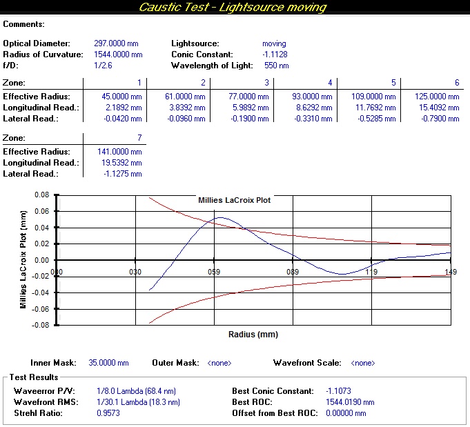
the outer and middle areas are back in tolerance, while the semi-central zone along with that is not processed “riser” a bit’ too much. Again I had to do a few laps in less, but it becomes difficult at these levels to determine how much work is sufficient to remove one / two dozens of nanometers glass…
Now I will try to lower the central area just enough to give a steady conical even more value to the in project.
If everything goes the right way , with a small session it should be possible in order.At that point, the processing can be regarded as completed, It could be groped to further improve the figure, This test permits, but I should have more precise mechanical instruments of my current.
“Move” within the tolerance trumpet, It means being able to accurately measure variations ( at least ) 2-3 microns on Y of the caustic. My setup ( Now the tester has been optimized to be able to easily change the eyepiece ) It allows me to easily measure the hundredth mm and, with a little’ fantasy and a good magnifying glass, I can go up to 5 thousandths and then do rely on the average of the readings:
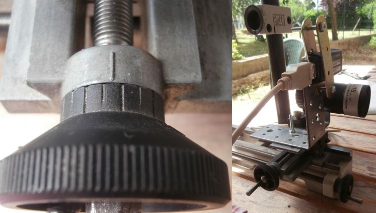
In the picture, the distance between two notches is 5 cents mm, as you can see measure the penny is not difficult…
Besides I can not go, which is why after reaching the tolerance is useless to try to improve, without adequate measuring instruments, roundings in the readings together with backlash, would be greater than the variation that you try to measure.
24 June 2015 at 21:15 #6238Is’ It was a very good speech on the most difficult part of the trumpet.
…Of course the tools subdiametro…in the hands of those who know how to use them are kind of “Magic wand”!Now the slight lowering of the hump remained, It should be easy (so it will automatically raise a little too low in the center tail improving a lot the lambda).
25 June 2015 at 22:42 #6259Really nice work, if you can take down the fault in the central part the result will be outstanding and lambda skyrocket…


I'm curious to also use this caustic tests, because I have doubts about the results of my tests made with Hartmann (doubts that may be dispelled by a second verification with another type of test course). But I not yet know how to make the meter with sensitivity, stability and accuracy required (I understand what I can disassemble, and reuse among everyday objects that can be recovered within)…26 June 2015 at 12:08 #6262Sometimes my consideration to freewheel on the meter construction, into account in sensitivity, stability and precision, all tending to greater possible simplicity (which it is never final, and it is always difficult to achieve).
The stability understood as repeatability of the measurements also depends on the thermal stability of the environment in which it operates.
An all-metal construction could perhaps be the ultimate, what it looks like this model……:
http://www.atm-workshop.com/tl-caustic.html…But I think even a construction plywood (crossed fibers give stability in all directions), used in a temperature environment favorably stable, It would still rise to the accuracy perhaps even more than hundredth. As indeed we see already in performing the Foucault test.
Certainly the construction metallic proposal is conceptually simple, but it requires milling operations that are not within the reach of DIY.
As well as the sensitivity and accuracy, a substantial mechanical advantage that presents consists in the fact that each of the two superposed carriages uses only three supports on its two tracks, two of which “autocentranti” on a same track by means of two Teflon shoes”V” overturned, and a simple support in the plane on the opposite binary.
And this feature was already contained in the tester suggested by Texereau, in favor of the principle that each plan is essentially determined by just three points.This three-point configuration always remove the smallest possible displacement of “wobble” around the axis of sliding of the rails.
Ma, no more talking about the project for which the link, in addition to the elimination of games on linear movements, in all of extreme precision equipment is necessary to eliminate the “backlash” who bring with them the adjustment screws that move those movements.
The simplest solution of this problem in the buildings DIY, It consists in not use screws for the movement of the carriages that do not have the same screw of the micrometer in free thrust; and to retain the basket against the thrust of the same micrometer screw, with a spring or a simple elastic.
The contact between the rod end of the push of the micrometer and the wall of the carriage, can be made point, and thereby significantly improved, interposing a small metal ball, which it can be locked in the head of the push pin of the micrometer by a small piece of heat-shrinkable plastic sheath.
Reduced to a minimum of handling problems and games of the two bogies, It remains the most difficult adjustment of their squareness, that must be the best possible.
But even this adjustment could not think is very critical as, 300F3 read on the inspection report, that the excursion of the total longitudinal measurement along the X axis for the mirror remains confined in less than 16mm (from 0,902 a 16.263mm), while the total excursion on the Y axis ranged from a minimum of 0.018mm to a maximum of 1,68mm
One last consideration that I am always useful, It is ballasting the tester or alternatively to attach it to a support table that is reasonably larger the size of the tester, because for example, already in Foucault I find it best to act in the dark with a tool that I know have made it difficult to move from its position.
26 June 2015 at 14:18 #6264Interesting considerations, in this sense for me has been very helpful to use the guides and the movements of a lathe which (it should) by definition have the orthogonal axes and adjusted with good precision. Another aspect is to use the source fixing instead of the mobile because the measures Dual.
last mirror update

They have intervened on two sectors:
– sub 90 mm, 10 rounds table with tangential ran to the radius 45 mm to pull down the central hump.
– sub 90 mm, 6 laps with racing tangential to the radius 125 mm to pull up the median depression.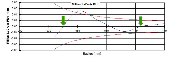
Also this time ( now is a custom ) I almost “go along” with the processing, another round and I would back out of the “Zona Franca” .
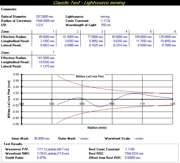
In each case the curve is all inside, although very little, I might have to stop here if it was not that “peak-to-valley” Central was too inviting to leave it unchanged
 In fact, the extension of the area to be corrected seemed tailor-made for the subs 90 mm , just what I'm using more often and which so far has given me the best results.
So I tried the last correction, the uncertainty was only the duration of the session so this time I kept “bass”:
– sub 90 mm, 4 laps with racing tangential to the radius 95 mm.
and finally a successful session ! the amount of work was exactly what I needed.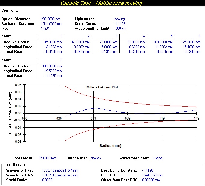
estimation error:
before taking to this good result it is important to estimate the measurement errors.
the extension of “"trumpet bell"” in the outer zone is less tolerant ( in this test configuration ) of 0,003 mm on the y-axis of caustic.-readings with the tester used do not reach this level of precision.
-Reliable reading and repeatable even after a long time approximated 0,01 mm. Although on the graduated scale of the knob “sees” which it is not exactly on the hundredth of a mm, it is impossible to determine this excess / defect visually. then consider 0,005 mm as the maximum read error .
-the extension of the slit eyepiece is slightly lower than 0,01 mm, means that the “centering” of the slit on the reticle may not contain an error greater than in 0,005 mm
mechanical games do not believe are influential, since the displacement of the carriage is done uniformly in one direction without ever reverse the direction in a same reading. If you get “too long” respect to the center of the slit, no going back with the knob ( which would inevitably lead with them the possible play of the threads ) but repeats the measurement.It therefore hypothesized that the maximum reading on the single error is 0,01 mm
therefore, estimating thousandth values was made by approximating the reading to the nearest cent for 10 readings each zone ( alternating the direction of displacement between a measure and the other ) and obtaining the average.
Therefore, if the maximum error on single reading remains 0.01 mm is reasonable to expect that the average of the readings is sufficient to halve the size of this error taking it to 0,005 mm
the this value further halves software as it does not require the distance between the slits but the Y coordinate from the optical axis that is exactly half of the measured value.The long final test tonight ( more than 3 hours to assess 5 minutes of work !!! ) It was repeated on two diameters at 90 ° respectively. the zone 2 and 4 reported differences 0,002 – 0,001 mm on the average of the readings ( 0,001 e 0,0005 software ) the others remained unchanged or were undetectable.
adding all these contributions and halving the value for the y coordinate, the maximum error to be put in quote is then reduced to 0,0026 mm.
This means that even if the estimated maximum error of all readings, the curve is maintained, however, within the tolerance zone, bringing with them a maximum variation of +/- 0.008 on the value of conical constant.As previously stated further improvements would not be measurable with my setup, then in the light of these considerations I can consider the completed mirror.

Last thing left for me to do before moving to the secondary is a nice “photoshoot” the Ronchi test which will be published shortly
 26 June 2015 at 14:52 #6265
Well, beyond the right considerations of the sensitivity tester you did, I must tell: crazy mirror !!!!!!!!!!!

Sincere congratulations.
Now comes the part that most interest me learn, given that it is a type of work that I have never done, ie the realizzazzione of a convex mirror…I can not wait.. 26 June 2015 at 17:01 #6266
..I am deeply impressed !!
I've never seen a lambda so crazy , which it is also shown by the diagram M-L thus centered in the trumpet of tolerances.
(I said, and I will, I'll print that all this discussion to collect it along with divers diameters instructions, studiarmela for good.. Is’ a “of which” too interesting)
26 June 2015 at 20:00 #6267Thanks for the compliments guys, but it was for a good part luck
 , still I would not be able to determine in advance how much work must be done to remove a certain amount of material… I gambled on “4 rounds” and it went so well… one or two laps more (I was going to get them ) and I failed leveling.
Anyway, the effect beyond “scenographic”, the value of lambda do not think is very useful in this moment. In fact, a less elevated correction does not affect on the goodness of the primary-secondary system, while the uncertainty on the value of conical constant ( which may be greater or less than that calculated error function which was mentioned before ) determines a “folding fan” of possible configurations of the secondary, all next to each other but different nonetheless .
So the questions I ask myself are:
-This value of K obtained and how reliable that we tolerance ?
-admitting that measurement errors millesimali significantly alter the value of K , even if the lambda remains good, as it affects this imprecision K on the primary-secondary system, in other words: there is the risk of having two very correct but outside mirrors optical design because the design values differ significantly from actual colors ?These are questions that begin to make me now to project myself towards the realization of secondary, work I've never done before ( Mirco makes two of us !
 ) but this does not worry me too much, I'm sure that for this other adventure there will be as always our Julius to show us the way…
  27 June 2015 at 12:22 #6269
I thank you for the confidence but, as to indicate the way…I would have serious doubts in a new and unknown space.
However, there would stop “send a cross toward the goal area” where you are you who decide whether my shot can be a “ball” good for ” the head” , or kick off.As regards the possible inaccuracy of K on the primary-secondary system, I believe that you do not run the risk of having two very correct but outside mirrors optical design, because I think there is a method of measurement …autocollimation type the entire system, maybe unwound at the Piedmont Company (Northek mi pare).
27 June 2015 at 14:53 #6272Really “Street” I've already indicated
 , if you remember the discrete amount of notes and texts translated on the secondary building / testing you sent me not long ago…
and, Massimo Boetto ( alias Northek ) She was so helpful and kind enough to invite the company to test the mirrors using their laboratory with flat mirror 600 mm. I take this opportunity to also thank him from these pages.
However this will be a test to be performed as a check on completion of mirrors, certainly not during processing, personally I find myself more 500 Km from Biella !29 June 2015 at 13:33 #6290In your use and consumption and about ostium argument concerning the construction of the secondary mirror and a convex hyperbolic, I just inserted in the Media, a new translation of the tutorial section of the book Lecleire, completing the previous translation, with the text explaining the important references that contained, in respect of the primary construction of the Cassegrain telescope Ø300 Coude F / D = 12, which the tutorial is the realization of the secondary.
I re-read everything and it does not seem to have written errors, (I hope that my brain has not taken the "common convenient shortcuts" reading that he wanted to read and not what was written).
-
AuthorPosts
- You must be logged in to reply to this topic.