- This topic has 142 replies, 6 voices, and was last updated 9 years, 6 months ago by
Giulio TiberinI .
-
AuthorPosts
-
17 January 2015 at 0:48 #5404
Update:
20 dried with the grain 220 They have been sufficient to eliminate residues 120. With this grain I tried to delay annoyed by adding small amounts of water every two to three minutes, up to bring the machining time even beyond the 15 minutes. It is coming off a good homogeneous surface that is also facilitating the work to the grain 320, which after the first 6 wets ( with a similar system of delayed dried ) It seems already at a good point, the percentage of residues of craterlets 220 it seems very low.
With this grain the surface begins to have, in addition to a form next to the sphere, a grinding fine enough to allow, with the wet mirror and a LED light, an easier measurement of the radius of curvature which is stationary to 1540 mm , with a read / measurement error ( or “focus” if you prefer ) I do not think exceed 2-3 mm more or less, clearly going ahead with the measures become more precise.
Tomorrow free day dedicated to scratching, account also archive 320
 17 January 2015 at 11:21 #5405
Is’ a very interesting job.
I think it will be very instructive after work, draw up a multiplication table summary page for times grits etc.; that deep, and despite Internet, Data are otherwise not available but can give you a pretty good idea who is going to face that new job.17 January 2015 at 13:30 #5406AND, the idea is and I am constantly updating the table with all the relevant data, but also to unite this table with the similar that could be extrapolated from your “diaries of realization” but also by “logbooks” in deabis, Mirco and all who wish to participate grattavetro.
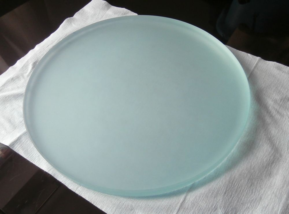
In this way you could create with time with a general table that summarizes the data relating to experiences / processing / different techniques depending also on the type of glass function, mirror diameters etc.… in short, it would be a nice database !24 January 2015 at 17:50 #5428Archived 320, I also completed the grinding with 500, a total of 20 prolonged dried using very little abrasive, about half a teaspoon.
This is the mirror at present:
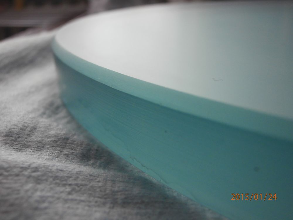
Always insist on the finishing of the edge because it is the main cause of rows and unwanted craters, with a little’ patience reason you can not have a simple cote, then the fine abrasives, in the absence of chipping, do the rest:
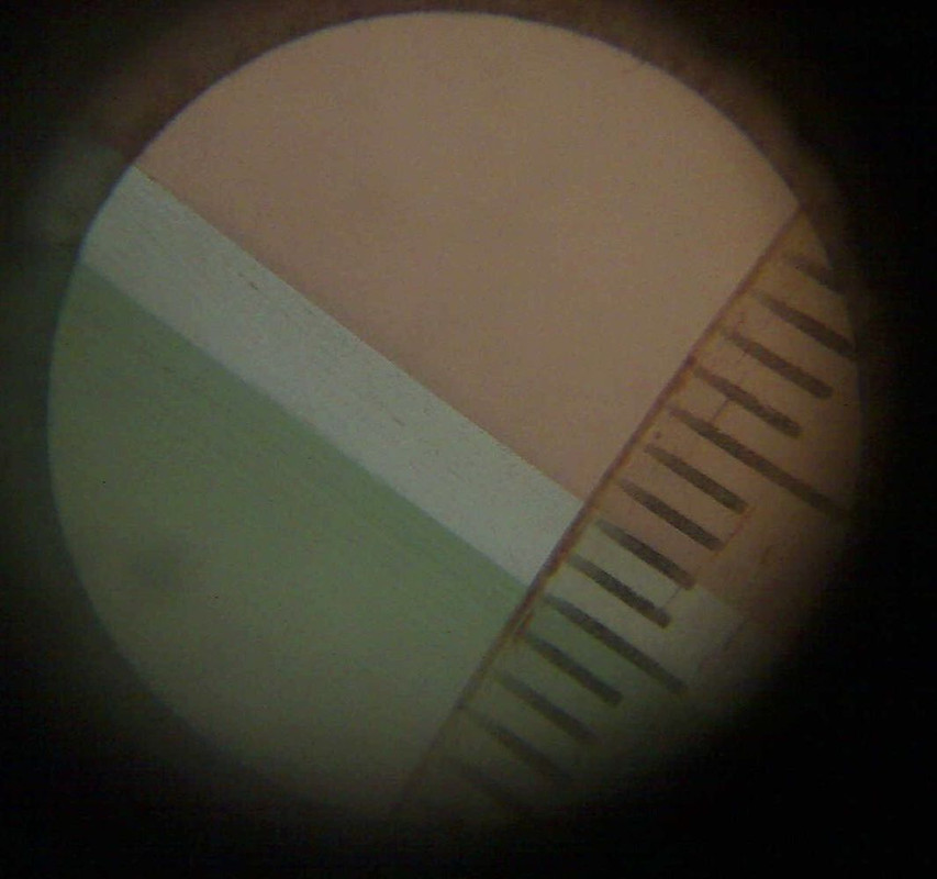
This is the view from the surface through a finder eyepiece ( very little ) and webcams putting in backlight the glass with the ceiling on the ceiling , This explains the ugly and impractical beige light that is seen in the background


the chamfer has a variable extension by 2.3 to 2.8 mm , because in some areas I had to insist more than others to eliminate some splinters inherited from higher grits, the concave surface is obviously that “beige”

A brief if part of the 800, last stop before the Cerox, then begin the pains !
 25 January 2015 at 8:43 #5432
Good job (and beautiful and definitive chamfer)!
25 January 2015 at 18:43 #5443I agree, just nice that edge, seems to machine-made…
 8 February 2015 at 17:18 #5509
Completed sanding with fine 20 dried grain 800, I like the surface, I can stop here…
Tomorrow I have an appointment with the waterjet for drilling glass…
 little question
  :
:
How great is that the hole ?
I mean, starting from the fact that the minimum and maximum limits of the practicable hole are given by the CPL project and encumbrance of the secondary lens hood which, in my case, have values respectively 45 mm ( cpl cone height of the mirror ) e 135 mm, what course to take ?:
1- trying to make a hole as small as possible, compatibly with the project, to maintain a greater integrity and mechanical strength of the glass block.
2- increase the size of the hole, always within the aforesaid limits, in order to work and correct almost exclusively the useful surface.to me you'd think that: “in an environment stat virtus”! (or also: “The safest” )
 9 February 2015 at 12:18 #5510
Let me start by saying my utter inexperience have never traveled that road. Then I can only peek at the work of others.
Taking into account, but nevertheless, the hole remains covered by obstruction proposed by secondary, but it increases the diameter of the tube piece lens cover that descends from its edge to touch the cone from the primary, and looking in the book of Lecleire (*) the constructional dimensions of Cassegrain Coude 300F12, I see the cone of light reaches high with a diameter of 79.33mm, and then choose a 95 mm diameter secondary intubated on a bell diameter 105 mm from a generous 80mm (this is the distance down from the secondary cone meets the incoming).The light reflected from the secondary cone will then, to affect primary to 24.17mm in diameter while the diameter of the hole is practiced 45.
In the book project also it includes the construction of a locking bit, Tertiary has always 95 mm diameter and support passes easily in the hole 45 mm.
*) The entire project complete manufacture and testing of four optical describes: primary – high school – tertiary level – closure sheet; as well as the mechanical design of the entire telescope.
clarifier little drawing:
http://s9.postimg.cc/o34aazedr/Cassegrai_Coud_300_F12.jpg9 February 2015 at 14:08 #5511Thanks Giulio, the diagram you understand that the choice is to keep the size of the hole rather small.
My project is more “open” and as I said the cone of cpl from the calculations is almost 50 mm ( focal plane is 32 mm ). This is my scheme even though the only geometric reflection is represented without considering the cpl. so I thought of making a hole 70 mm, also to have margin to insert the sleeve on which screw the center of the primary lens hood.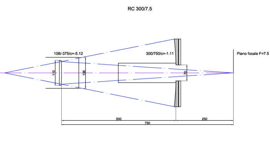
by the way,small mechanical brackets, according te the hood-sleeve assembly must be integral with the mirror, and then with the collimation or movements must be independent and fixed to the support base of the cell, and then integral with the focuser group ?
 9 February 2015 at 16:32 #5512
I do not know. But for simplicity, “a naso”, I believe that the lens hood fisserei the tube to the primary, leaving separate and free the tube behind the focuser….Of course, ignoring any negative consequences
 12 February 2015 at 11:43 #5517
Cutting performed, now at the center of the mirror is a nice hole 70 mm !
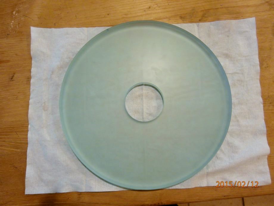
It took longer to calibrate the machine to the center of the mirror, that to make the cut.
This is the video of the cut with waterjet:
A perfect execution, allow me to thank the guys Calestrini firm Sangiustino and Mauritius in particular, which he was kindly offered to perform the cutting overseeing the machine setup, with setting the water pressure, cutting speed, etc.. they were also interested in the outcome of this process since it had never drilled a Cassegrain primary…
 12 February 2015 at 13:41 #5520
BEAUTIFUL And INTERESSANTISSIMO..ed fast!
Two spontaneous questions I “go up” of enblèe:
1) The cut starts (it seems) the center, It creates an initial hole autonomously passage? (by poor initial boil, it seems so)
2) The water contains abrasive or is “smooth”?A eye seems that the track of the cut has eroded a width of perhaps 2mm or so; Conti to put the “plug” securing it in its place for the following processing with the usual optical glue casting pitch based, ; Or Let's work the mirror with hole?
It would be interesting to find out if the cut have emerged voltages before insesistenti. (see article by Pierre Strock
http://strock.pi.r2.3.14159.free.fr/Ast/Art/Tension.htmlHowever, I repeat: Very interesting!
12 February 2015 at 13:56 #5522Dinìmenticavo that the analsi of the tensions that requires two polarized lenses, it's possible “disassembling” Use a pair of glasses…(“and reuses!”) paid 4 euro with movie ticket tridimesionale.
But from personal experience I must say that many internal tensions characterizing such as glass “hardened” side of the car, or certain structures of glass constructions type aeroporuali covers and similar, They are already well visible only wearing polarized sunglasses.The three advantages of “slow” polarized 3D film, It is that they are Piane; Transparent and without colorings.
12 February 2015 at 13:58 #55241- Exact, the hole has been independently created at the center. This choice was made because, after having made a test on another similar glass, They have seen that the initial hole is more extended 1 mm compared to the rest of the cut and is also the time “more critical” for the stability of glass ( so I'm told )
2- the water does not contain abrasive, it's simply “shot” pressure ( I have no idea what the value ). They told me that the glass is more difficult to cut than metals as an excessive initial pressure I could die or literally split

Absolutely right, congratulations for the visual measurement, the track is slightly less than two mm. Two millimeters is in fact the minimum drilling measure that guarantee.
About the cap, I do not know, I was thinking of asking you

for the internal tensions, Now I'll try to read ( to translate ) the article with the help of Google.
12 February 2015 at 14:49 #5526I had never seen me in action not a waterjet…and I not thought he had such a cutting speed that is seen by cutting a slab of 20 mm thick !!!

As it appeared the cutting edge just finished processing? there were scheggiette or something? or it was lovely Net? -
AuthorPosts
- You must be logged in to reply to this topic.