- This topic has 190 replies, 7 voices, and was last updated 8 years, 3 months ago by
 Massimo Marconi.
-
AuthorPosts
-
21 March 2015 at 18:40 #5652
Hi Massimo,
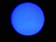
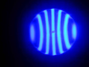
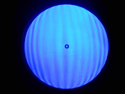
the third photo e’ made with a lattice printed on glossy paper and I played with the effects a bit to see how it looked,the others are made with a copper lattice made by me21 March 2015 at 19:10 #5653Ok Maurizio, try taking more photos with both this lattice and the copper one ( as long as it is not made of transparent nylon ), trying to:
– decrease and distribute the intensity of the light ( not the crack ), sanding the led glass ( if you use a led ) or even shielding with thin or semi-transparent paper ( like parchment paper ) between source and fissure.
– as mentioned before it is important to minimize the distance ( lateral ) between source and grating, I would not be wrong, but it seems to me that in these photos there is some “perspective” that there shouldn't be, the image must be beautiful on the front.
21 March 2015 at 19:38 #5654Ok I'll do some tests ,but how much should be the distance between source and grating?
and why it can lead to these kinds of errors21 March 2015 at 20:02 #5655The distance must be as small as possible, moving away from the optical axis all the extra-axial aberrations are introduced ( distortion, coma, astigmatism ) which do not exactly give these kinds of errors, but they still alter the extent of surface defects by adding others “physiological” than adding up, amplify those on the mirror.
If the distance is great, the aberrations assume higher values than the real defects, preventing a correct evaluation of the shape.22 March 2015 at 15:34 #5656I did some tests by shielding the LED light with various types of paper and I took some photos.
The premium 3 they are made with the copper lattice and the others with the printed lattice
http://s3.postimg.cc/wmj5cvqhv/IMG_20150322_130513.jpg
http://s27.postimg.cc/dl6p18rtf/IMG_20150322_130440.jpg
http://s9.postimg.cc/r95z92az3/IMG_20150322_130436.jpg
http://s9.postimg.cc/hkx4jo5jj/IMG_20150322_124453.jpg
http://s21.postimg.cc/3w4fvkpwn/IMG_20150322_124219.jpg
http://s2.postimg.cc/sbv0myk09/IMG_20150322_122249.jpg
http://s11.postimg.cc/ahzruah9f/IMG_20150322_112123.jpg
http://s29.postimg.cc/yal5y0mc7/IMG_20150322_124100.jpg22 March 2015 at 15:43 #5657I forgot this made with the printed lattice
http://s12.postimg.cc/jo7ruzz71/IMG_20150322_110223.jpg22 March 2015 at 17:27 #5658hello Maurizio, I still think there is something to fix in the lattice and in the LED / slot.
Look at this previous image of yours:
http://s7.postimg.cc/ha0xwivnv/intrafocale2.jpg
In this photo the shaded bands are black, as they should be, if they take on a faint color or there is interference with the illuminated bands, it means either that the LED is too intense or that the slot is too wide or that the reticle is not good.The pictures you made do not show the same flaws, only the general trend is similar, which means that the test has something that skews the results.
I know it's not easy, unfortunately, gaining confidence and optimizing Ronchi requires a certain commitment and even time, however, it is necessary in order to evaluate the surface you are working on.
Czech to check all components paying attention to:
– slot to the maximum of the same width as the bands ( lattice 4 lines / mm = slot 0,125 mm )
– frosted led ( better ) or shielded
– parallel grating and slit for better contrast of bands
– minimum source / grating distance.
 22 March 2015 at 19:51 #5659
Hi Massimo,thanks for your patience.
And anyway, I sanded the LED with the 800 (and after your advice I also screened it) from the beginning,the distance between source and grating e’ circa 3,5 cm ,the parallelism between lattice and slot is certainly not perfect but I think it is good, the slot I tried to tighten it and also to widen it compared to 0.125mm , however, I also used the printed grid. But one thing is’ certain that somewhere I'm wrong.
And surely those are wrapped 2 neurons I have.22 March 2015 at 20:18 #5660Don't worry Maurizio, it is normal that the first few times is like this… if I show you my first Ronchi, they looked like abstract paintings !
The first ones you did had a better setting, would have to work with that setup and try to optimize it.
If you sanded the slide, that's fine, it's okay so no additional shielding is needed.
The distance of 3,5 cm is fine, you just have to try again, you will see that little by little we take our hand…
A question, the images in the photos are the same as you see by eye “live” ?22 March 2015 at 20:28 #5661Same pictures
23 March 2015 at 16:15 #5664hello Maurizio,
I also agree with Massimo's suggestions. It is best for you to first arrange the tester in order to obtain better images. This is not so much for an aesthetic purpose, but in order to better interpret the shape of the mirror. It would be frustrating for you too to go and interpret and maybe try to correct an error that doesn't actually exist, but which seems to exist by interpreting the irregularities of the lines which are actually due to other factors that have nothing to do with the true shape of the surface…
In addition to the reticle and the light source, also check that the edge of the blades you use to make the slit is nice smooth and regular. If it seems to be even slightly jagged, pass the blade for a couple of minutes on very fine sandpaper, perhaps resting on a nice flat surface such as glass or marble… 24 March 2015 at 13:23 #5673
This weekend I will try to understand where the problem lies by evaluating all the suggestions that have been given to me.
24 March 2015 at 20:13 #5678@Maurizio: I do not go crazy for Ronchi, and then I used very little and therefore I have a few suggestions about.
With regard to the realization of the test have to say that the contrast improves with the use of a well-net pattern between light and dark, but we must (as for Foucault) also align well its vertical bars that are parallel to the slot. And to do this it puts a magnifying glass from a few diopters instead observer's eye, and on that lens it will form the image of the slit which will align well to it the reticle.This is the difference in contrast between the Ronchi grating attached to the book “astronomical optical clipboard” Luigi Ferioli:
250F5
1 With Ex Book extrafocal reticulum
 [/url]
 2 With Ex Book intrafocale reticulum
 [/url]
 Compared to this “smortino” carried out with a slide of the original lattice above:
3 with grid photographed on slide
 [/url]
 Anyway, returning to your mirror test would say that it is in accordance with the approach to the parable procedure. I would say that there is a raised edge that is good thing; and I seem to see a sort of central hole with a step that starts from the prior right fringe and the second left.
But I would say that everything is in accordance with “work in progress”. And the “medicine” It is to insist in applying the runs with ooze forward back 1/3 center over center (to standardize the entire figure and eliminate the step); and keeping to a minimum the ooze right-left (not to transform the high board in one shot back). Of course the races should be applied with adaptation of the tool pitch pressure, of right hardness compatible with the ambient temperature. The tool absolutely full diameter and devoid of any fraying of pitch protruding from its circumference. The del'utensile rotation around the table is also important to avoid, and / or being able to correct errors zone….in conclusion, all things already known.
Then I would recommend you to start early to use Foucault, to get a bit of practice.
If you maintain a loyal trends to those basic rules, you can not do form errors, so theoretically you could well do without Ronchi. But Foucault can not do without, if you want to know what, and where there are jobs.24 March 2015 at 21:45 #5681Giulio, the second Ronchi is beautiful ! apart from the quality of the dish and the surface ( it can also be seen from Ronchi
 ) there is an enviable tester setup !
Maurizio, do not be alarmed, it is not necessary to go that far to make a reliable test, Giulio's photos are however interesting because they are indicative of the different potentials of the various lattices.
Returning to Maurizio's mirror, I agree on the evaluation of the general trend of the fringes but, as Mirco says, it is not clear whether the flaws “locals” are such or only apparent.
I would like to understand if what you see is roughness / deformation , because if so it is useless to try to improve the tester, the problem is on the patina, if instead the tester is the problem then it is better to wait before any corrective action.
25 March 2015 at 15:09 #5683hello Giulio,but when you say” the strokes must be applied with adaptation pressure of the tool pitch ” it means that if in the pitch-tool adaptation I put about 10 kg ,then when I start 1/3 COC I have to apply roughly the same pressure?
-
AuthorPosts
- You must be logged in to reply to this topic.